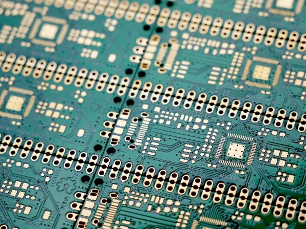
I will go over a review of a white paper that I have been reading. The white paper is named, “High-Reliability PCB Design Tips For Aerospace And Other Harsh Environments,” written by an individual or team of experts at Advanced Assembly. Within the review, I will discuss what I see as a problem statement. Then go over the proposed work as well as the previous work. I will then dwell on the risks and challenges and talk about the innovation behind the proposed work.
Problem Statement
All printed circuit boards that are manufactured must meet design-related standards. Of particular concern is the reliability of the boards since their longevity is uncertain. What can affect this longevity, however, is thermogenic periods and average operating temperature. There are issues with the expanding temperature of the boards, one of which is the Coefficient of Thermal Expansion being affected by glass fibers that are different than what the PCB is used to. Also, there are failures between the layer of the dielectric and the wall of the via due to shear-related stress from the enhanced temperature. Therefore, there is a need to produce a way to mitigate these issues.
Proposed Work
The white paper proposes using solder-resistant layers as barriers between the pad of the solder and the via near the pad. Vias that are filled and capped are utilized where an epoxy fill material has a layer of copper on top of it. This is in the case of vias underneath pads. Also, engineers have found a variety of other alloys that can become solders for PCBs at an average temperature.
Prior Work
In the past, the quality of PCBs was easier to spot than the reliability of them. Most Printed Circuit Boards have a CTE (Coefficient of Thermal Expansion) that is mostly anisotropic. The weft-and-warp fibers (fiberglass strands) can help lower temperature expansion in-plane, but not out-of-plane. Not all these fibers are the same. Also, unfilled vias are usually added to a thermal pad, leading to problems down the line.
Risks and Challenges of This Proposed Work
Even though the proposed work for enhancing reliability for PCBs seems to have significant benefits, there are, however, some risks and challenges along with it. The first is the fact that poor adhesion of solder-resistant layers can lead to delamination, exposing copper traces, which will increase the likelihood of corrosion or short circuits. Poor definition on the PCB may result if the solder-resistant layer is not applied properly. This can cause solder bridges between pads, even with components that are fine pitched. The two main challenges regarding this are repair and rework of solder-resistance layers and making sure that surface finishes are compatible. Plating copper on top of epoxy can bring about adhesion problems. Mechanical stress can occur while there is thermal cycling, once the COEs change between epoxy and copper. Also, the integrity (electrical and mechanical) of the copper can be reduced due to the voids creating weak spots in the deposition of epoxy or copper. The two main challenges of these issues are preparing the surface of the epoxy properly and having a thickness that is even when trying to get deposition of uniform copper. Vias that are small in diameter are susceptible to the formation of voids during the process of copper electroplating. This is especially true when the vias are not disinfected or prepared properly. Vias can fail when there are extreme temperature stresses during the thermal cycling of copper electroplating. Uniform plating within tiny vias is hard to achieve, which would result in fills that are not complete and copper thickness that is uneven. The challenges involved are controlling the thickness of copper during electroplating in small vias and making sure the via can manage conditions of operation and the assembly’s mechanical stresses. The risks of other alloys being used besides Sn-63/Pb-37 mixtures include poorer wetting properties, which lead to weaker solder joints, melting points that are higher, fragile solder joints leading to failure, and issues with not being compatible with solder that is lead-free. The challenges include adjustments to the soldering process, these new alloys meeting industry standards, and the formation of corrosion and whisker of tin.
Innovation of This Proposed Work
The proposed reliability aspect of PCB design makes for a significant innovation in the field, which offers a more proactive and comprehensive method for ensuring the reliability of printed circuit boards. With solder-resistant layers, filled vias, and safe alternate alloys, safety risks are then minimized, allowing an increase in reliability. Along with this reliability comes enhanced longevity. Also, thermal temperatures can be controlled to cause less damage to the boards.
Leave a Reply